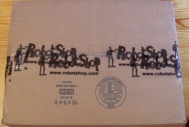
The box the kit came in was a bit over stuffed and bulging on one side, but once I opened it up, I found this was due to the amount of protective padding they have placed around the actual kit box.
 |
| RobotShop Box containing my Kit |
In the box was my beautifully packaged Inventors Kit from SparkFun Electronics.
 |
| My SparkFun Inventors Kit |
 |
| My Arduino Uno Rev 3 micro controller (right) and "breadboard" on the left. |
For more information I strongly urge you to just check Wikipedia or do a quick google search.
The Inventors Kit also contains 10 yellow LEDs, 10 red LEDs, one RGB LED (an LED that contains Red, Green and Blue components). An RGB device can produce many colours.
Additionally the kit contains a piezo element that can be used to produce sounds, a temperature sensor, several push buttons, a servo, a DC motor, a soft potentiometer (a thin potentiometer whose resistance changes by pressing at different points along the potentiometer), a flex sensor (where the resistance of the device changes as the device is stretched/bent), a diode (basically a one way valve for electricity), a transistor (ampiflier/switch), a relay (a switch), a photoresistor (a resistor whose resistance changes with the amount of light that hits it), a regular potentiometer (an adjustable voltage divider (like a volume knob) , and a shift register (a type of integrated circuit).
Okay, well now to some of the fun that I had on the first day.
First I played with turning an LED ON and then OFF. Then using the kit instructuions I stepped it up and did this:
I modified the code slightly to bring the the side by side pairs on at the same time instead of following an order that went down the left side, then down the right side.All this took was modifying the codes for loops.
Next I played with the piezo element and following the instructions and sample code created the sample circuit and made it play the first line from Twinkle Twinkle Little Star. With more time/personaly interest, you could complete the full song and numerous other songs. All you need to do is determine the notes that make up the song, the frequency of those notes, and thus the period and time to activate the piezo for.
Okay, well that is all for me from day 1. Next I think I"ll look at the RGB LED and the softpot (soft potentiometer), there is an example experiment showing how to use the softpot to change the color of the RGB LED. After that example I think I'll start moving on to my ultimate goals, controlling my DSLR. First I'll start by controlling an old digital camera I have and then move up from there, as I really really don't want to fry my DSLR.
Until next time.... 0100100001100001011101100110010100100000011001100111010101101110001000000110110101101001011000110111001001101111001000000110001101101111011011100111010001110010011011110110110001101100011010010110111001100111001000000111100101101111011101010111001000100000011101110110111101110010011011000110010000101110.....
....hint convert from binary to ASCII.
neerrrrdddd.
ReplyDelete